A Programmer's Note on TraCI_tls, TraCI, and SUMO
Introduction
TraCI_tls is a simple SUMO model developed as part of SUMO’s tutorial on TraCI. It is a perfect starting point for anyone who is interested in using SUMO and the TraCI tool. After going through the tutorial material given here, we find that the tutorial may be improved in terms of helping the user to understand the model from a software’s point of view. The official tutorial also does not provide a complete list of wiki pages that are essential to help the user to understand the model. Therefore, we provide this study note to supplement the TraCI_tls tutorial. Source codes of this model is hosted here.
First let’s take a look at the file structure of TraCI_tls:
.
+-- data
|   +-- cross.nod.xml
|   +-- cross.edg.xml
|   +-- [cross.typ.xml]
|   +-- cross.con.xml
|   +-- cross.netccfg
|   +-- cross.net.xml
|   +-- cross.det.xml
|   +-- cross.rou.xml
|   +-- cross.sumocfg
|   +-- cross.out
+-- embedded
|   +--
+-- plain
|   +--
+-- embedded.py
+-- runner.py 			main script
+-- tripinfo.xml
We will begin by going through the files contained in the data folder.
Building the Road Network
Each SUMO model is built on a network of roads, junctions, traffic lights, and other infrastructure items such as induction loop detectors. Compared to the vehicles and their movements, these are the static elements of the model. For TraCI, it is good practice to separate these definitions from the Python scripts in a data folder. Let’s take a look at what’s in this folder.
Nodes and Edges
Nodes and edges are the most basic elements of a SUMO model. Nodes are the reference points on a map, i.e. the “A” and “B” in “Going from A to B”. Edges are the paths connecting these reference points.
First, let’s look at cross.nod.xml:
<?xml version="1.0" encoding="UTF-8"?>
<nodes xmlns:xsi="http://www.w3.org/2001/XMLSchema-instance" xsi:noNamespaceSchemaLocation="http://sumo.dlr.de/xsd/nodes_file.xsd">
   <node id="0" x="0.0" y="0.0"  type="traffic_light"/>

   <node id="1" x="-500.0" y="0.0" type="priority"/>
   <node id="2" x="+500.0" y="0.0" type="priority"/>
   <node id="3" x="0.0" y="-500.0" type="priority"/>
   <node id="4" x="0.0" y="+500.0" type="priority"/>

   <node id="51" x="-510.0" y="0.0" type="priority"/>
   <node id="52" x="+510.0" y="0.0" type="priority"/>
   <node id="53" x="0.0" y="-510.0" type="priority"/>
   <node id="54" x="0.0" y="+510.0" type="priority"/>
</nodes>
This file defines a list of 9 nodes, each has a unique id, that are “0”,”1”,”2”,”3”,”4”,”51”,”52”,”53”,”54”. The x and y locations of each node are also given in the definition of each node. Each node also has a type attribute. Without consulting more documentation, it is easy to understand what “traffic_light” means being node 0’s type. It must be a junction controlled by traffic lights. But what does priority mean for all the other nodes? After consulting this documentation on SUMO’s XML schema, it appeared that this is related to the priority attribute of edges, so let’s take a look at our next file cross.edg.xml:
<?xml version="1.0" encoding="UTF-8"?>
<edges xmlns:xsi="http://www.w3.org/2001/XMLSchema-instance" xsi:noNamespaceSchemaLocation="http://sumo.dlr.de/xsd/edges_file.xsd">
   <edge id="1i" from="1" to="0" priority="78" numLanes="1" speed="19.444" />
   <edge id="1o" from="0" to="1" priority="46" numLanes="1" speed="11.111" />

   <edge id="2i" from="2" to="0" priority="78" numLanes="1" speed="19.444" />
   <edge id="2o" from="0" to="2" priority="46" numLanes="1" speed="11.111" />

   <edge id="3i" from="3" to="0" priority="78" numLanes="1" speed="19.444" />
   <edge id="3o" from="0" to="3" priority="46" numLanes="1" speed="11.111" />
	...

</edges>
From this file we have definition of a bunch of edges, each again has a unique id such as “1i” for the edge going from node “1” to node “0”. To answer our earlier question regarding the priority typed nodes, we see that each edge has a priority attribute which has numerical values meaning that edges can be compared according to their prioritys. In this model, edges going into the juction (node 0), i.e. “*i” edges, have a higher priority of 78 than those exiting the junction, i.e. “*o” edges which have a lower priority of 46.
Apart from priority, we also have numLanes and speed as attributes for edges. These are easy to understand literally. But this file has lots of repetitive codes, and this is not ideal from a programming point of view. Not to worry though, SUMO has this covered with a *.typ.xml file which we will take a look at in the next section.
Before we finish this section, let’s quickly summarise what we know about the definitions of nodes and edges so far of TraCI_tls with this illustration:

Further reading: On node types (extract from here:):
priority: Vehicles on a low-priority edge have to wait until vehicles on a high-priority edge have passed the junction.traffic_light: The junction is controlled by a traffic light (priority rules are used to avoid collisions if conflicting links have green - light at the same time).right_before_left: Vehicles will let vehicles coming from their right side pass.unregulated: The junction is completely unregulated - all vehicles may pass without braking; this may cause collisionstraffic_light_unregulated: The junction is controlled by a traffic light without any further rules. this may cause collision if unsafe signal - plans are usedpriority_stop: This works like a priority-junction but vehicles on minor links alway have to stop before passingallway_stop: This junction works like an [All-way stop]rail_signal: This junction is controlled by a rail signal. This type of junction/control is only useful for rails.zipper: This junction connects edges where the number of lanes decreases and traffic needs to merge zipper-style (late merging).rail_crossing: This junction models a rail road crossing. It will allow trains to pass unimpeded and will restrict vehicles via traffic - signals when a train is approaching..traffic_light_right_on_red: The junction is controlled by a traffic light as for type traffic_light. Additionally, right-turning vehicles may drive in any phase whenever it is safe to do so (after stopping once). This behavior is known as right-turn-on-red.
Define edge types with a *.typ.xml file
Indeed, there is no cross.typ.xml file included in this model, but there could have been one and it would have looked like this:
<?xml version="1.0" encoding="UTF-8"?>
<types>
   <type id="go_in_to_junction" priority="78" numLanes="1" speed="19.444"/>
   <type id="come_out_of_junction" priority="46" numLanes="1" speed="11.111"/>
</types>
With the addition of this cross.typ.xml file, the cross.edg.xml file can be simplified as:
<?xml version="1.0" encoding="UTF-8"?>
<edges xmlns:xsi="http://www.w3.org/2001/XMLSchema-instance" xsi:noNamespaceSchemaLocation="http://sumo.dlr.de/xsd/edges_file.xsd">
   <edge id="1i" from="1" to="0" type="go_in_to_junction" />
   <edge id="1o" from="0" to="1" type="come_out_of_junction" />

   <edge id="2i" from="2" to="0" type="go_in_to_junction" />
   <edge id="2o" from="0" to="2" type="come_out_of_junction" />

   <edge id="3i" from="3" to="0" type="go_in_to_junction" />
   <edge id="3o" from="0" to="3" type="come_out_of_junction" />
	...

</edges>
Compare this to the original version:
<?xml version="1.0" encoding="UTF-8"?>
<edges xmlns:xsi="http://www.w3.org/2001/XMLSchema-instance" xsi:noNamespaceSchemaLocation="http://sumo.dlr.de/xsd/edges_file.xsd">
   <edge id="1i" from="1" to="0" priority="78" numLanes="1" speed="19.444" />
   <edge id="1o" from="0" to="1" priority="46" numLanes="1" speed="11.111" />

   <edge id="2i" from="2" to="0" priority="78" numLanes="1" speed="19.444" />
   <edge id="2o" from="0" to="2" priority="46" numLanes="1" speed="11.111" />

   <edge id="3i" from="3" to="0" priority="78" numLanes="1" speed="19.444" />
   <edge id="3o" from="0" to="3" priority="46" numLanes="1" speed="11.111" />
	...

</edges>
You can see that edge attributes such as priority and numLanes have been extracted and grouped together in the cross.typ.xml file. This is useful when you have many edges of the same type, and it is also a good practice from a programming point of view.
Further reading: To get a full list of the attributes an edge may have, consult SUMO’s documentation on its *.typ.xml file here.
Connect edges with a *.con.xml file
We now have 8 edges all associated with node 0, a traffic_light typed node. These edges have yet to be connected together, i.e. rules are yet to be defined to route vehicles from one edge to another. Let’s see how this is done in TraCI_tls:
<?xml version="1.0" encoding="iso-8859-1"?>
<connections xmlns:xsi="http://www.w3.org/2001/XMLSchema-instance" xsi:noNamespaceSchemaLocation="http://sumo.dlr.de/xsd/connections_file.xsd">
	<connection from="1i" to="2o"/>
	<connection from="2i" to="1o"/>
	<connection from="3i" to="4o"/>
	<connection from="4i" to="3o"/>
</connections>
The code for connections are self-explanatory with from and to to establish a link between two edges which we illustrate below:

Indeed, from and to are the most essential attributes of a connection. Other attributes are also available for defining a connection:
| Attribute | Description |
|---|---|
| fromLane | <int>, the lane index of the incoming lane (numbers starting with 0) |
| toLane | <int>, the lane index of the outgoing lane (numbers starting with 0) |
| pass | <bool>, if set, vehicles which pass this (lane-2-lane) connection) will not wait |
| keepClear | <bool>, if set to false, vehicles which pass this (lane-2-lane) connection) will not worry about blocking the intersection. |
| contPos | <float>, if set to 0, no internal junction will be built for this connection. If set to a positive value, an internal junction will be built at this position (in m) from the start of the internal lane for this connection. |
| visibility | <float>, specifies the distance to the connection [in m.] below which an approaching vehicle has full sight of any other approaching vehicles on the connection’s foe lanes (i.e. vehicle can accelerate if none are present). Defaults to 4.5m. Note that a too low visibility (<=0.1m.) will prevent vehicles from crossing a minor link. For major links the attribute has no effect, currently. |
| uncontrolled | <bool>, if set to true, This connection will not be TLS-controlled despite its node being controlled. |
According to these attributes, there are a lot you can do with a connection, but let’s concentrate on TraCI_tls for now.
Further reading on connections is available here .
Generate *.net.xml, with netconvert and *.netccfg
Before we dive deeper in the data folder, let’s take a look at what assets we have got so far for the TraCI_tls model:
.
+-- data
|   +--  cross.nod.xml 		nodes, junctions
|   +--  cross.edg.xml 		edges, paths, roads
|   +--  [cross.typ.xml] 		edge types
|   +--  cross.con.xml			connection between edges
|   +--  cross.netccfg
|   +--  cross.net.xml
|   +--  cross.rou.xml
|   +--  cross.sumocfg
|   +--  cross.det.xml
|   +--  cross.out
...
With the 4 checked files, we are now ready to put the nodes, edges, and connections together to construct a complete “network”. In order to do this, first we need to write a network configuration file named cross.netccfg:
<?xml version="1.0" encoding="UTF-8"?>

<configuration xmlns:xsi="http://www.w3.org/2001/XMLSchema-instance" xsi:noNamespaceSchemaLocation="http://sumo.dlr.de/xsd/netconvertConfiguration.xsd">

    <input>
        <node-files value="cross.nod.xml"/>
        <edge-files value="cross.edg.xml"/>
        <connection-files value="cross.con.xml"/>
    </input>

    <output>
        <output-file value="cross.net.xml"/>
    </output>

    <report>
        <verbose value="true"/>
    </report>

</configuration>
cross.netccfg and cross.netc.cfg are acceptable suffixes to SUMO’s GUI. If you are not using the GUI then this file can have any name as long as you give it correctly to netconvert.cross.netccfg is very literal with input and output files specified in the first two sections. The verbose option in the report section controls the verbose output behaviour of netconvert.
On a command line, execute the following command to generate a cross.net.xml file.
netconvert -c cross.netccfg
netconvert is a SUMO binary just like sumo and sumo-gui. If you compiled SUMO from source then this together with all other SUMO binaries should be in your bin folder, for example in my case this is the ~/sumo-0.29.0/bin/ folder. If you make install-ed, then these binaries will be located somewhere like /usr/local/bin/. Issue a which netconvert command to find out where it is.
cross.netccfg file is to make calling netconvert earlier for the user. Without cross.netccfg, an equivalent result can be achieved by executing
netconvert -n cross.nod.xml -e cross.edg.xml -x cross.con.xml -o cross.net.xmlon command line.
netconvert automatically, it is worth taking a look at cross.net.xml as it gives detail on the default behaviours of the netconvert tool. We will see more on this file later on.Further reading on netconvert is available here.
Place Detectors with *.det.xml
<e1Detector id="0" lane="4i_0" pos="450" freq="30" file="cross.out" friendlyPos="x"/>
Further reading on detectors is available here, detectors TraCI
Network Summary
Let’s summarise the process of generating a network with the following illustration:

Our progress through the data folder looks like this:
.
+-- data
|   +--  cross.nod.xml 		nodes, junctions
|   +--  cross.edg.xml 		edges, paths, roads
|   +--  [cross.typ.xml] 		edge types
|   +--  cross.con.xml			connection between edges
|   +--  cross.netccfg			network configuration
|   +--  cross.net.xml 		network
|   +--  cross.det.xml 		detectors
|   +--  cross.rou.xml
|   +--  cross.sumocfg
|   +--  cross.out
...
Note that cross.det.xml is not part of the network for a SUMO model. We will see it in action later on.
Defining Traffic
Having constructed the road network in the previous section, the stage is now ready for our actors.
Add Vehicles and Routes with *.rou.xml
To get traffic moving on our network, we first need to define vehicles and routes for vehicles to travel along. This is done in the cross.rou.xml file:
<routes>
        <vType id="typeWE" accel="0.8" decel="4.5" sigma="0.5" length="5" minGap="2.5" maxSpeed="16.67" guiShape="passenger"/>
        <vType id="typeNS" accel="0.8" decel="4.5" sigma="0.5" length="7" minGap="3" maxSpeed="25" guiShape="bus"/>

        <route id="right" edges="51o 1i 2o 52i" />
        <route id="left" edges="52o 2i 1o 51i" />
        <route id="down" edges="54o 4i 3o 53i" />

        <vehicle id="left_0" type="typeWE" route="left" depart="0" />
        <vehicle id="left_1" type="typeWE" route="left" depart="2" />
        <vehicle id="right_2" type="typeWE" route="right" depart="3" />
        <vehicle id="right_3" type="typeWE" route="right" depart="4" />
        ...

</routes>
In SUMO, a route is a sequence of connected edges. In this file, we see that a route is defined with the route label, and its edges attribute contains a space-delimited string of edge names giving the sequence of edges a vehicle is to travel on along this route. In this model, as their id suggest, we have two routes traveling horizontally in each direction, and one from north (top) to south (bottom). All three routes travel through the junction at node “0”.
As well as routes, vehicles and their type vTypes are also defined in cross.rou.xml. In TraCI_tls, we have two types of vehicles: typeWE for horizontally traveling vehicles and typeNS for vertical traveling vehicles.
We can see that the length of this file is dependent on the number of vehicles included in the simulation and that implies that this file could be significantly longer than the other files in the data folder. Therefore, it is preferable to generate this file with a script. This takes us to the runner.py file in the root folder of this model.
Further reading on the definition of vehicles, vehicle types, and routes is available here
Main Script runner.py
We see from cross.rou.xml that defining vehicles by hand is a labouring task, so we now introduce runner.py which generates traffic information according to given distributions. runner.py is a script with code logic rather than the XML-based data files we have seen so far from this model. Let’s look at this script by sections.
Generate Traffic
First, to continue our observation from the cross.rou.xml file, let’s take a look at the generate_routefile function:
def generate_routefile():
    random.seed(42)  # make tests reproducible
    N = 3600  # number of time steps
    # demand per second from different directions
    pWE = 1. / 10
    pEW = 1. / 11
    pNS = 1. / 30
    with open("data/cross.rou.xml", "w") as routes:
        print("""<routes>
        <vType id="typeWE" accel="0.8" decel="4.5" sigma="0.5" length="5" minGap="2.5" maxSpeed="16.67" guiShape="passenger"/>
        <vType id="typeNS" accel="0.8" decel="4.5" sigma="0.5" length="7" minGap="3" maxSpeed="25" guiShape="bus"/>

        <route id="right" edges="51o 1i 2o 52i" />
        <route id="left" edges="52o 2i 1o 51i" />
        <route id="down" edges="54o 4i 3o 53i" />""", file=routes)
        lastVeh = 0
        vehNr = 0
        for i in range(N):
            if random.uniform(0, 1) < pWE:
                print('    <vehicle id="right_%i" type="typeWE" route="right" depart="%i" />' % (
                    vehNr, i), file=routes)
                vehNr += 1
                lastVeh = i
            if random.uniform(0, 1) < pEW:
                print('    <vehicle id="left_%i" type="typeWE" route="left" depart="%i" />' % (
                    vehNr, i), file=routes)
                vehNr += 1
                lastVeh = i
            if random.uniform(0, 1) < pNS:
                print('    <vehicle id="down_%i" type="typeNS" route="down" depart="%i" color="1,0,0"/>' % (
                    vehNr, i), file=routes)
                vehNr += 1
                lastVeh = i
        print("</routes>", file=routes)
From this we can see that indeed the cross.rou.xml file in the data folder is produced by this function. The definitions of the 2 vTypes and 3 routes are written as is. Then, at each time step (i/N), a vehicle is generated for each of the 3 routes according to its respective probability (pWE, pEW, pNS). The route attributes given to these 3 vehicles ensure they are assigned to the correct route, and the depart attribute specifies the time step at which they join the network. Additionally, the vehicles traveling from north to south is given the red colour (color="1,0,0") to distinguish themselves.
Control Traffic with Traffic Lights and Induction Loop
Next, let’s take a look at the run() function
def run():
    """execute the TraCI control loop"""
    step = 0
    # we start with phase 2 where EW has green
    traci.trafficlights.setPhase("0", 2)
    while traci.simulation.getMinExpectedNumber() > 0:
        traci.simulationStep()
        if traci.trafficlights.getPhase("0") == 2:
            # we are not already switching
            if traci.inductionloop.getLastStepVehicleNumber("0") > 0:
                # there is a vehicle from the north, switch
                traci.trafficlights.setPhase("0", 3)
            else:
                # otherwise try to keep green for EW
                traci.trafficlights.setPhase("0", 2)
        step += 1
    traci.close()
    sys.stdout.flush()
5 methods of traci are called in this control loop:
| Method | Description |
|---|---|
| trafficlights.setPhase(string,int) -> None | Set the given traffic light to the given phase. Read more after this table. |
| simulation.getMinExpectedNumber() -> int | Returns the number of vehicles which are in the net plus the ones still waiting to start. This number may be smaller than the actual number of vehicles still to come because of delayed route file parsing. If the number is 0 however, it is guaranteed that all route files have been parsed completely and all vehicles have left the network. |
| simulationStep(int=0) | Forces SUMO to perform simulation. If given input is 0, SUMO performs exactly one time step. Otherwise SUMO performs the simulation until the given time step is reached. If the given time step is smaller than or equal to the current simulation step then SUMO does nothing. Read more here. |
| inductionloop.getLastStepVehicleNumber(string) -> int | Returns the number of vehicles that were on the named induction loop within the last simulation step. |
| traci.close() | Performed at the end of the simulation. Stop the simulation and SUMO. |
Let’s focus on the trafficlights.setPhase method. For a start, what does traci.trafficlights.getPhase("0") == 2 do? We know that it sets the traffic light at node 0 to phase 2, but what exactly is phase 2? And how is it giving green to EW traffic? Going through the model files we went through for this model, our only definition relevant to this traffic light is <node id="0" x="0.0" y="0.0" type="traffic_light"/> in cross.nod.xml. Therefore the phase data of this junction must have a default behaviour, but what is the default behaviour of this type of function? The answer to this question lies in the cross.net.xml file which includes the following definition (tlLogic) for this traffic light:
<tlLogic id="0" type="static" programID="0" offset="0">
    <phase duration="31" state="GrGr"/>
    <phase duration="6" state="yryr"/>
    <phase duration="31" state="rGrG"/>
    <phase duration="6" state="ryry"/>
</tlLogic>
This teels us that phase 2 is <phase duration="31" state="rGrG"/>. From this, we understand that each character in the state attribute corresponds to a positive number of connections (as put in the official documentation: “a one-to-n dependency between signals and links is implemented, this means each signal may control more than a single link - though networks generated by NETCONVERT or NETGENERATE usually use one signal per link”, with “link” meaning “connection”). We know that we have 4 connections defined in cross.con.xml and they corresponds to the 4 characters in the state attribute of each phase.
The next question is which character corresponds to which connection? Again we need to consult cross.net.xml:
<connection from="1i" to="2o" fromLane="0" toLane="0" via=":0_3_0" tl="0" linkIndex="3" dir="s" state="o"/>
...
<connection from="2i" to="1o" fromLane="0" toLane="0" via=":0_1_0" tl="0" linkIndex="1" dir="s" state="o"/>
...
<connection from="3i" to="4o" fromLane="0" toLane="0" via=":0_2_0" tl="0" linkIndex="2" dir="s" state="o"/>
...
<connection from="4i" to="3o" fromLane="0" toLane="0" via=":0_0_0" tl="0" linkIndex="0" dir="s" state="o"/>
The linkIndex attributes of these 4 connections give us their order in the state string, meaning for example phase 0 is:
- the connection from “4i” to “3o” is “r”
- the connection from “3i” to “4o” is “G”
- the connection from “2i” to “1o” is “r”
- the connection from “1i” to “2o” is “G”
We illustrate the use of linkIndex as below:

Further Reading:
getLastStepVehicleNumber(self, loopID)
getLastStepVehicleNumber(string) -> integer

Returns the number of vehicles that were on the named induction loop within the last simulation step.
Boilerplates of runner.py
Thirdly, let’s look at the header section of runner.py:
from __future__ import absolute_import
from __future__ import print_function

import os
import sys
import optparse
import subprocess
import random

# we need to import python modules from the $SUMO_HOME/tools directory
try:
    sys.path.append(os.path.join(os.path.dirname(
        __file__), '..', '..', '..', '..', "tools"))  # tutorial in tests
    sys.path.append(os.path.join(os.environ.get("SUMO_HOME", os.path.join(
        os.path.dirname(__file__), "..", "..", "..")), "tools"))  # tutorial in docs
    from sumolib import checkBinary
except ImportError:
    sys.exit(
        "please declare environment variable 'SUMO_HOME' as the root directory of your sumo installation (it should contain folders 'bin', 'tools' and 'docs')")

import traci
The try block tries to locate and include the TraCI python module traci and sumolib from the $SUMO_HOME/tools directory.
Finally, once import has been completed, the script triggers the sumo model and then execute the run() function to establish the connection with the following code section:
if __name__ == "__main__":
    options = get_options()

    # this script has been called from the command line. It will start sumo as a
    # server, then connect and run
    if options.nogui:
        sumoBinary = checkBinary('sumo')
    else:
        sumoBinary = checkBinary('sumo-gui')

    # first, generate the route file for this simulation
    generate_routefile()

    # this is the normal way of using traci. sumo is started as a
    # subprocess and then the python script connects and runs
    traci.start([sumoBinary, "-c", "data/cross.sumocfg",
                             "--tripinfo-output", "tripinfo.xml"])
    run()
Here, we that after the binary has been located, routes and vehicles are generated by generate_routefile(), then a sumo server is started and a connection is established between the model and TraCI, before finally the controls are executed with the run() function. We also see the use of cross.sumocfg when the sumo binary is called.
<?xml version="1.0" encoding="UTF-8"?>

<configuration xmlns:xsi="http://www.w3.org/2001/XMLSchema-instance" xsi:noNamespaceSchemaLocation="http://sumo.dlr.de/xsd/sumoConfiguration.xsd">

    <input>
        <net-file value="cross.net.xml"/>
        <route-files value="cross.rou.xml"/>
        <additional-files value="cross.det.xml"/>
    </input>

    <time>
        <begin value="0"/>
    </time>

    <report>
        <verbose value="true"/>
        <no-step-log value="true"/>
    </report>

</configuration>
cross.sumocfg is similar to cross.netccfg in functionalities. It provides the parameters for the sumo/sumo-gui binary rather than to the netconvert tool which is aided by cross.netccfg.
Further Reading: additional files
Start the simulation in sumo-gui
By executing python runner.py, by default the GUI version of sumo is triggered:
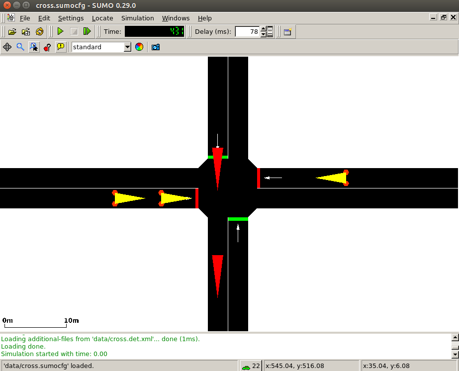
Adjust the “Delays” parameter and start the simulation by clicking on the button.
Simulation Summary
Finally, we summarise the process and structure of TraCI_tls with this illustration:
